645-DRM Board Installation QRS

This procedure covers installing the 645-DRM Board, including dipswitch settings, flash compatibility, and reader-type compatibility. The board diagram shows where to land reader wiring for standard 5-wire readers and OSDP readers.
INSTALL REQUIREMENTS
-
To install a 645-DRM board, the Controller CPU board must be running a minimum Flash v10.5.6 (or higher).
-
The 645-DRM is currently shipped with Flash v11.0.5. You do not need to update this flash if the controller is running v10.5.6 (or higher).
-
645-DRM can be installed along with 635-series daughter boards.
-
645-DRM cannot be installed as a Remote Door Module using RS-485.
-
645-DRM does not support the traditional method of flashing through the I2C Data Bus (J13).
-
IMPORTANT: Future enhancements of the 645-DRM will require the DRM flash to be upgraded. When future flash updates are required, you must use the Factory Test Station on a 635-CPU running v11.0.5 or higher and connected at J2). See 635-FTS Daughter Board Flash Procedure QRS for more information.
-
LOCK SURGE SUPPRESSION: You must install surge-suppression at the Lock. The Lock must have a separate power supply. See Figure 3 and Figure 4 on page 2.
INSTALL STEPS
-
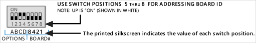
Set DIPSWITCH (SW2) to a unique/unused Board-ID Address (1-15 is valid; Factory Default is 15).
NOTE: The Value of each dipswitch position is marked on the board silkscreen.
|
FIGURE 1 : 645-DRM DIPSWITCH |
|
|
|
|
-
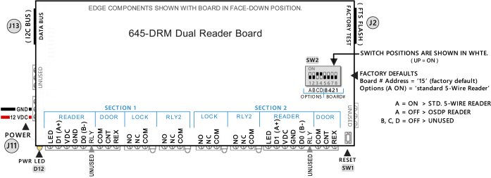
Set DIPSWITCH (SW2) for the Reader Type …
-
For a Standard 5-wire Reader Type: Option A = ON / UP ( B, C, D = OFF; factory default )
-
For an OSDP Reader Type: Option A = OFF / DOWN ( B, C, D = OFF )
-
OSDP Reader must be configured for 9600 Baud, Reader Number 0 (zero), and non-secure channel.
Use the method provided by the reader manufacturer to configure reader settings. -
In the System Galaxy software, the OSDP Reader port must be set to use “Wiegand Standard”.
FIGURE 2 : 645-DRM EDGE COMPONENTS
-
-
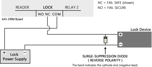
INSTALLING SURGE-SUPPRESSION DIODE (mandatory)
-
Land Lock wires as needed NC = FAIL SAFE & NO = FAIL SECURE
-
The Lock device must use a separate power supply.
-
You must install the surge-suppression diode in reverse-polarity at the Lock – shown in Fig. 3 below.
FIGURE 3 : SURGE-SUPPRESSION DIODE – SHOWN INSTALLED IN REVERSE POLARITY
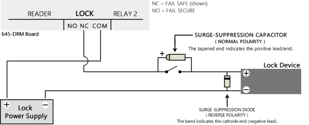
INSTALLING SURGE-PROTECTOR CAPACITOR (conditionally mandatory)
-
IF you are installing a switch (switch/relay/component) that breaks or closes circuit to the lock device, you must install the provided surge-protector capacitor ( pn: T322B105K035AT7200 ).
-
Observe polarity when installing the capacitor – shown in Fig. 4 below
FIGURE 4 : SURGE-SUPPRESSION CAPACITOR – SHOWN INSTALLED IN NORMAL POLARITY